By Yogish Sekhar & Kat Fox
This blog post covers ZeroRISC’s recent contributions implementing one-time programmable (OTP) memory zeroization to achieve FIPS 140-3 compliance. We did this in partnership with Rivos Inc, using the code at git hash 032df24, as part of our commitment to aligning open silicon with important industry security standards. A future post will describe how we’re advancing that mission further via the GlobalPlatform organization’s Trusted Open Silicon Task Force.
In this technical post, we’ll address what the FIPS 140-3 requirements for zeroization are, how we improved the prior OTP design to meet these requirements, and what the hardware verification process looked like.
Zeroization and FIPS 140-3: Erasing Secrets Safely
There are many ways a secure device can reach its end of life, including planned decommissioning of a functioning device or return of a defective one. Regardless of context, it’s critical that no cryptographic secrets remain on a device once it’s taken out of service and changes hands.
The typical process for this is zeroization: at a device’s end of life, a special routine is run on the device to zero out all sensitive regions of OTP. In practice, this means blowing all the remaining OTP fuses, leaving the memory cleared.
While this may sound like a straightforward operation, there are a number of details that make zeroization tricky to implement:
- Blowing fuses requires a lot of charge, so fuses need to be blown word-by-word
- Due to manufacturing variations, a small fraction of OTP fuses may simply not blow
- If power loss happens during zeroization, the device may be in an in-between state where some secrets are still accessible but others aren’t
- The device must be able to reliably determine whether zeroization completed
As such, zeroization is a good target for standardization. FIPS 140-3 dictates a number of requirements regarding zeroization, summarized in the Implementation Guidance for FIPS 140-3 sections 9.7.A and B. At a high level, these state that zeroization…
- …must overwrite all secrets with 0s, 1s, or random data (assertion AS09.30).
- …must inform the device to treat zeroized values as inaccessible (assertion AS09.29).
- …must erase any integrity values like checksums for secrets (assertion AS09.28).
- …must somehow indicate a completion status to a user (assertion AS09.33).
It is important to note that FIPS 140-3 extends the prior zeroization requirements of critical security parameters (CSPs) to also include all unprotected sensitive security parameters (SSPs), regardless of their security level, along with public keys. To see what meeting these requirements looks like in practice, let’s review our approach to OTP zeroization.
Practical Zeroization: How to Tidy Up OTP
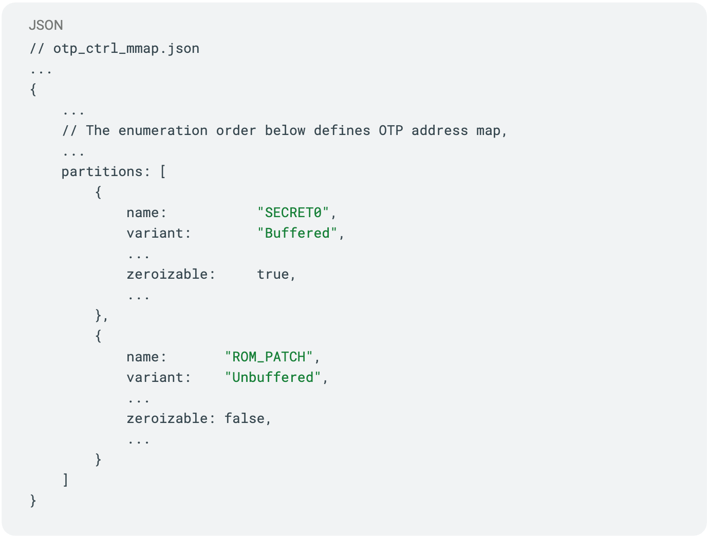
As a first practical detail, we need to consider which parts of OTP should be zeroized in the first place. In order to store different kinds of device state, the OTP is split up into partitions, some of which contain secrets that should be zeroized, and some of which contain data that shouldn’t.
One example is the lifecycle partition, which records whether a chip has been deployed or if it’s been returned to manufacturer. Since the chip relies on this partition’s data to determine what should be accessible, zeroizing this partition would render a chip unusable.
As such, we add a zeroizable control field to the memory map for the OTP partitions; by changing this flag, the hardware enforces whether or not the zeroization mechanism can clear that partition:
During generation of the OTP RTL, we check this field when generating partition offsets, allocating a 64-bit field after the digest indicating whether zeroization has happened. Each zeroizable OTP region then looks like
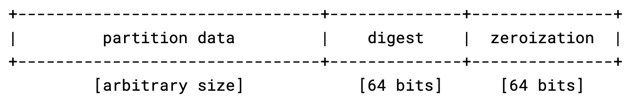
where the last 64 bits can be all set to 1 (a blown fuse) to indicate that the partition has been zeroized.
To address the possibility of “stuck at zero” fuses during zeroization, we use a dedicated integrator-tunable parameter for what fraction of bits correctly cleared indicates a proper zeroization. If the OTP controller detects say >90% of fuses blown in the zeroization marker, then it’s reasonable to consider the partition truly zeroized.
For triggering zeroization itself, the OTP’s existing Direct Access Interface (DAI) is used with the addition of a new command field. By setting the ZEROIZE bit in DIRECT_ACCESS_CMD register, the OTP controller will zeroize values at a provided address and then return the number of fuses which actually ended up blown. By sequentially clearing each zeroizable OTP field using this DAI interface, a dedicated zeroization application can clear all secrets from the chip without having to worry about manually tracking zeroization markers.
As a last detail, it may seem inconsequential whether we set the zeroization marker for a partition before clearing the partition or after, as by the end of zeroization the result is the same. It turns out that this ordering is actually important both to security and certifiability: by setting the marker before clearing the partition, we prevent power loss mid-zeroization from leaving partially-zeroized partitions marked as usable by the processor.
Checking our Work: Verifying our Zeroization Logic
By the time OTP zeroization happens, a device could be in any number of states. As part of implementing OTP zeroization, we need to be certain that whatever state the device is in before zeroization, it is both deterministically usable/non-usable per operator policy and properly zeroized afterward.
To do this, we took a pure Universal Verification Methodology (UVM) approach with constrained-random stimulus, targeted sequences, and comprehensive functional coverage. For a review of UVM, there are many excellent guides online including this one from ChipVerify.
How We Verified It: A Config-Aware UVM DV Strategy
The aim of this effort was two-fold: to ensure that zeroization works regardless of state, and that even under adverse conditions, the OTP is left in a functioning state. As such, two key virtual sequences were introduced:
- otp_ctrl_zeroization_vseq.sv, which triggers zeroization under stress (DAI, CSR access)
- otp_ctrl_zeroization_with_checks_vseq.sv, which adds post-zeroization integrity and access checks
To ensure coverage across various chip states, these sequences randomly select:
- Target OTP partition (vendor, creator, etc.)
- Partition offset (start, middle, digest, or zeroization trigger address)
- Whether the partition is zeroizable or not
Additionally, the scoreboard and monitor were enhanced to
- Track pre-zeroization state per partition
- Verify post-zeroization expected values (zeroized -> all 1s, non-zeroized -> unchanged)
- Detect illegal reads from secret partitions (even if data is zeroized)
Using these changes, we can ensure that the OTP zeroization mechanism has been tested for every possible combination of factors that it could encounter in the real world.
Functional Coverage: Closing the Loop
To ensure coverage, we added two config-aware covergroups to ensure 100% scenario closure.
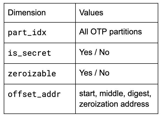
The first is zr_dai_cmd_cg, which handles zeroization DAI command coverage. This covergroup samples every DAI access during and after zeroization with the following dimensions:
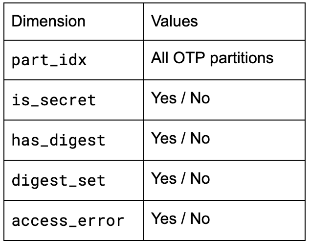
The second, complementary covergroup is zr_partition_read_cg, which handles post-zeroization read behavior by cross-covering five dimensions for each partition:
Config-Driven DV: One Testbench, Any OTP Layout
In order to make this testing framework maintainable, it needs to adapt to any changes to the OTP layout. As such, we made the testbench configuration-driven: any changes to the OTP memory map are reflected in the virtual sequences, scoreboard, and covergroups. Upon building the testbench, the HJSON OTP memory map is parsed and the resulting partitions are used to fill in Mako templates for the testbench source files:
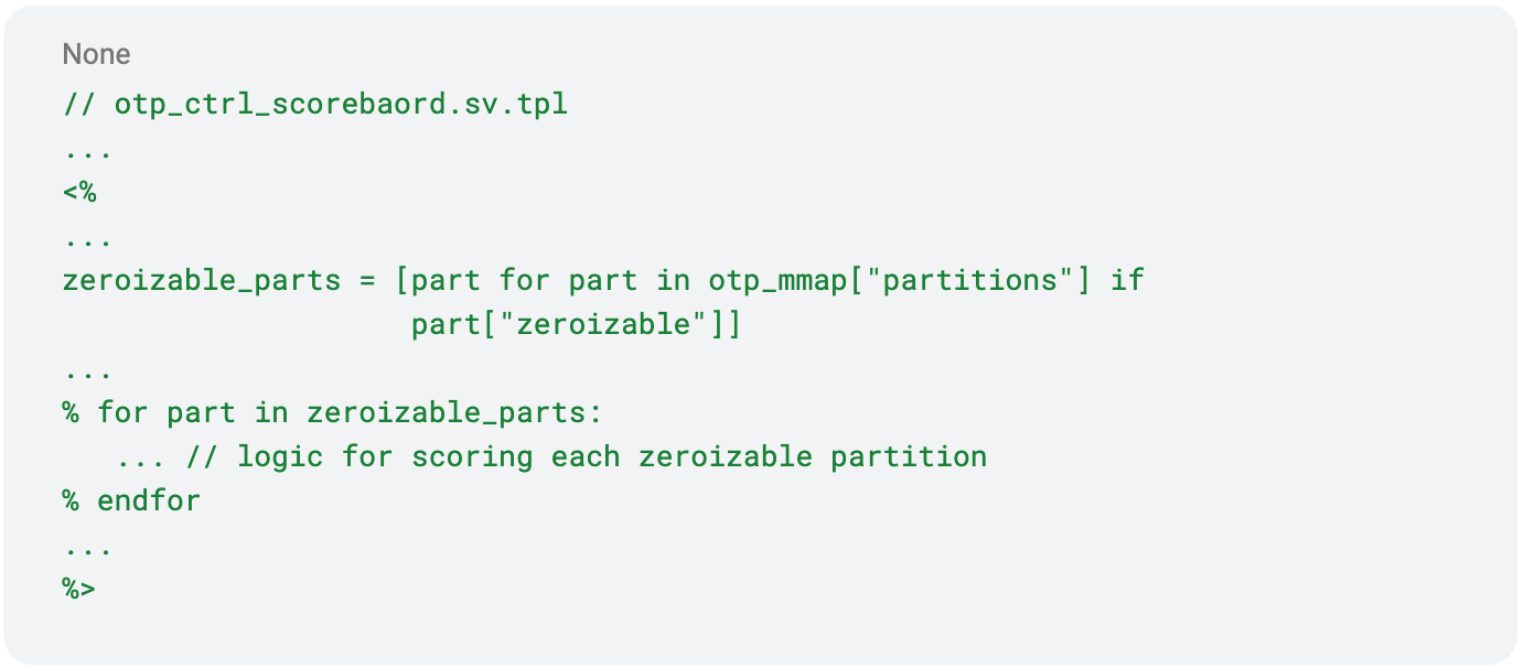
Using this approach, the test bench is able to immediately adapt to updates to the OTP memory map, ensuring that what’s tested is exactly in sync with what will be taped out.
Result: Provable Zeroization
Together, these elements of our testbench allow us to continuously ensure that the OTP zeroization mechanism works exactly as intended. Below is a table of the properties we were able to verify regarding this mechanism:
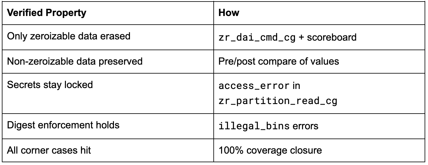
Because of the configuration-driven design of the test bench, we are able to continuously verify these properties for any integration of the OTP controller.
Conclusion
When working with secure systems, conceptually simple tasks such as OTP zeroization can require a remarkable degree of care and effort to incorporate properly. Practical security considerations, standards compliance, and maintainability all need to play a part in engineering design choices, and rigorous digital verification is essential.
If you’re interested in learning more about ZeroRISC and our open silicon approach to device integrity, drop us a note at info@zerorisc.com.